联系我们
- 客服1:项目改造
- 客服2:备品备件
- 电话:189-1774-1718
- Q Q:1066932912
- 邮箱:sales@zhongji-tech.com
产品中心
美国TRANS.TEK传感器
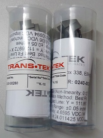
现货供应美国TRANS.TEK传感器0240等系列产品,欢迎询价美国TRANS.TEK,TRANS.TEK传感器,TRANS传感器,美国TRANS,0240-0028。产品简述

现货供应美国TRANS.TEK传感器0240等系列产品,欢迎询价美国TRANS.TEK,TRANS.TEK传感器,TRANS传感器,美国TRANS,0240-0028。

美国TRANS-TEK位移传感器、TRANS-TEK线性传感器、TRANS-TEK角位移传感器、TRANS-TEK线速度传感器、TRANS-TEK角位移传感器、TRANS-TEK传感器,至今已有30多年的历史。TRANS-TEK主要重点是线性传感器,它是基于lvdt (线性可变差动变压器)的技术。TRANS-TEK线性位移测量,制成品完整系列的直流-直流和交流-交流lvdts ,测量范围0.010英寸至60英寸,标准配置包括高温度,高压力,小机构,以及低成本的版本。TRANS-TEK计量lvdts可在范围从0.01至20英寸,交流-交流,直流-直流版本可供选择。TRANS-TEK角位移传感器,轴驱动装置,具备了提供直流电压或4-20马输出信号的比例,以角位移,范围达300度与准确性的,以0.05 %的足尺可供选择。TRANS-TEK线速度传感器提供直流电压成正比的输出瞬的对象被用来衡量。这些模拟传感器不需要励磁电压,并且是非常坚固。速度可衡量的线性范围从0.50至24英寸。为配合传感器的使用,TRANS-TEK公司还提供各种各样的信号调理电子产品,电源供应器,和传感器指标数据。
例举部分型号如下:Trans-Tek线速度传感器 100系列: 0100-0000 0100-0001 0101-0000 0101-0001 0111-0000 0111-0001 0112-0000 0112-0001 0113-0000 0113-0001 0114-0000 0114-0001 0122-0000 0122-0001 0123-0000 0123-0001 0124-0001 0125-0001 0126-0001 0127-0001 ; Trans-Tek角位移传感器 600系列:0600-0000 0601-0000 0602-0000 0603-0000 0603-0001 0603-0002 0603-0003 0603-0004 0603-0005 Trans-Tek角位移传感器 0605系列; Trans-Tek位移传感器(DC-DC) 200系列: 0200-00000/1/2/3 0200-00010/1/2/3 0201-00000/1/2/3 0201-00010/1/2/3 Trans-Tek位移传感器(DC-DC) 240系列: 0240-00000/1/2/3 0241-00000/1/2/3 0242--00000/1/2/3 0243--00000/1/2/3 0244-00000/1/2/3 0245-00000/1/2/3 0246--00000/1/2/3 0246-00005 ; Trans-Tek传感器(DC-DC) 350系列: 0350-0000 0350-0010 0351-0000 0351-0006 0352-0000 0353-0000 0354-0000 0355-0000 0356-0000 3/8" AC LVDTs Trans-Tek Series 230: 0230-0000 0231-0000 0232-0000 0233-0000 0234-0000 0235-0000 0236-0000 0237-0000 Trans-Tek Spring Actuated AC-AC LVDTS, Series 310-320: 0315-0000 0316-0000 0317-0000 0318-0000 0319-0000 0320-00000321-0000 0322-0000 ; Trans-Tek 3/8" Gauging AC-AC LVDTS, Series 330 0330-0000/1 0331-0000/1 0332-0000/1 0333-0000/1 0334-0000/1。
TRANS - TEK代理 TRANS - TEK厂家 TRANS - TEK价格 TRANS - TEK经销 TRANS - TEK型号 TRANS - TEK现货
TRANS - TEK agent TRANS - TEK manufacturer TRANS - TEK price TRANS - TEK distribution TRANS - TEK model TRANS - TEK spot
TRANS - TEK, TRANS - TEK sensors, TRANS - TEK displacement sensor, TRANS - TEK linear sensor, TRANS - TEK angular displacement sensor, TRANS - TEK linear velocity sensor, TRANS - TEK absolute angular displacement sensor, TRANS - TEK sensor
SPECIFICATIONS - ELECTRICAL
| MODEL NUMBER | 0240-0000 | 0241-0000 | 0242-0000 | 0243-0000 | 0244-0000 | 0245-0000 | 0246-0000 | 0246-00005 |
| WORKING RANGE, ± Inches (mm) | 0.050 (1.27) | 0.100 (2.54) | 0.250 (6.35) | 0.500 (12.7) | 1.00 (25.4) | 2.00 (50.8) | 3.00 (76.2) | 3.00 (76.2) |
| MAX. USABLE RANGE, ± Inches (mm) | 0.075 (1.78) | 0.150 (3.75) | 0.375 (9.53) | 0.750 (19.1) | 1.50 (38.1) | 2.75 (69.8) | 3.25 (82.5) | 4.00 (101) |
| INPUT, VDC | 6.0 Min. to 30 Max. | 9.0 Min. to 30 Max. | ||||||
| NOMINAL F.S. OUTPUT, ±VDC with unloaded output | ||||||||
| @ 6 VOLT INPUT | 1.3 | 2.4 | 1.8 | 3.1 | 4.6 | 3.9 | 3.3 | N/A |
| @ 15 VOLT INPUT | 3.4 | 6.4 | 4.8 | 8.3 | 12.1 | 10.2 | 8.7 | 10 |
| @ 24 VOLT INPUT | 5.5 | 10.4 | 7.8 | 13.5 | 18.7 | 16.5 | 14.1 | 16.3 |
| @ 30 VOLT INPUT | 7.0 | 13.0 | 9.7 | 17.0 | 24.8 | 20.7 | 17.7 | 30.5 |
| INPUT CURRENT | 8.3 mA @ 6 Volt input to 52 mA @ 30 Volt input | |||||||
| 2 NON-LINEARITY | ±0.5% Full Scale Over Total Working Range, ±1.0% Full Scale Over Maximum Usable Range | |||||||
| INTERNAL CARRIER FREQUENCY, Hz | 13000 | 12000 | 3600 | 3400 | 3200 | 1500 | 1400 | 1400 |
| % RIPPLE, RMS (nominal) | 0.7 | 0.7 | 0.8 | 0.8 | 0.8 | 1 | 1 | 1 |
| OUTPUT IMPEDANCE, Ohms | 2500 | 3500 | 5200 | 5500 | 5600 | 5500 | 5600 | 5600 |
| FREQ. RESPONSE (3 dB down), Hz | 300 | 140 | 115 | 110 | 100 | 110 | 75 | 75 |
| TEMPERATURE RANGE | -65°F to +250°F (-54°C to +121°C) | |||||||
| RESOLUTION | Infinite | |||||||
NOTES:
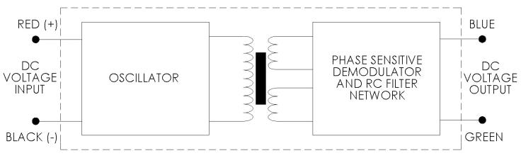
- Polarity of excitation must be observed for proper function. Reversal will not damage the unit.
- Load Impedance of 50 KOhms minimum required for proper operation.
- Output polarity will be positive on one side of null, negative on the other side of null.
- Transducers are calibrated at 24 VDC.
- Blue lead is more positive with respect to the Green lead when the core is moved toward the lead end.
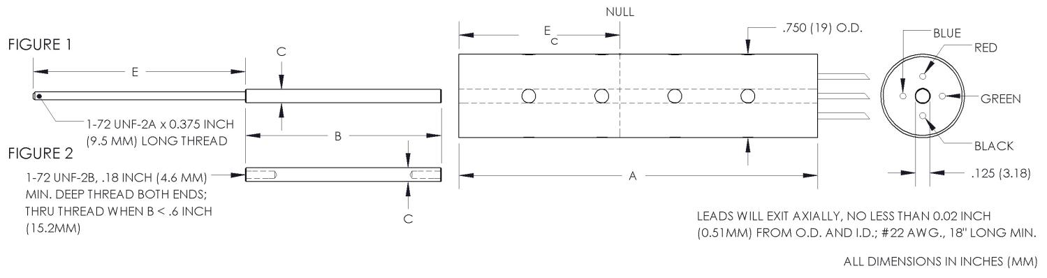
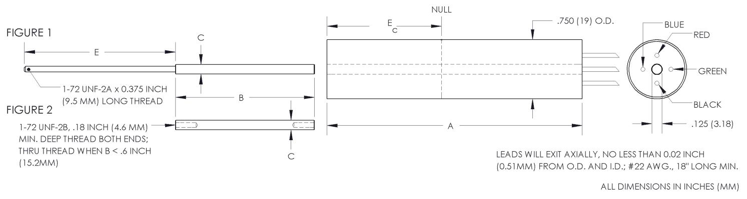
DIMENSIONAL DIAGRAM
SPECIFICATIONS - MECHANICAL
| MODEL* | LINEAR RANGE | BODY LENGTH, A | ELECTRICAL CENTER, Ec | BODY MASS | CORE LENGTH, B | EXTENSION LENGTH, E |
| ±Inches (mm) | Inches (mm) | Inches (mm) | Grams | Inches (mm) | Inches (mm) | |
| 0240-0000__ | 0.05 (1.27) | 0.87 (22.1) | 0.34 (8.64) | 55.8 | 0.56 (14.2) | 1.9 (48.3) |
| 0241-0000__ | 0.10 (2.54) | 1.12 (28.5) | 0.46 (11.7) | 59.2 | 0.75 (19.1) | 1.9 (48.3) |
| 0242-0000__ | 0.25 (6.35) | 3.21 (81.5) | 1.44 (36.6) | 121.4 | 1.75 (44.5) | 1.9 (48.3) |
| 0243-0000__ | 0.50 (12.7) | 3.71 (94.2) | 1.69 (42.9) | 132.2 | 1.87 (47.5) | 2.4 (60.9) |
| 0244-0000__ | 1.00 (25.4) | 4.71 (120) | 2.19 (55.6) | 156.2 | 2.00 (50.8) | 3.2 (81.2) |
| 0245-0000__ | 2.00 (50.8) | 8.21 (209) | 3.94 (100) | 235.4 | 3.50 (88.9) | 5.2 (132) |
| 0246-0000__ | 3.00 (76.2) | 10.52 (267) | 5.09 (129) | 293 | 3.50 (88.9) | 8.4 (213) |
| 0246-00005 | 4.00 (101.6) | 10.52 (267) | 5.09 (129) | 293 | 2.00 (50.8) | 9.1 (231) |
* Model numbers ending with a “_” have multiple core options. All standard units will end with a 0 indicating a core assembly. This core assembly consists of a core brazed to an extension rod that terminates in 1-72 UNF-2A threads. If an option is not selected, option 0 will be provided.
CORE OPTIONS
| Core Assembly Ref Fig. 1 | Threaded Core Ref Fig. 2 | |||
| OPTION 0 | OPTION 1 | OPTION 2 | OPTION 3 | |
| MODEL |
C = 0.120* (3.05mm) |
C = 0.099* (2.51mm) |
C = 0.120* (3.05mm) |
C = 0.099* (2.51mm) |
| 0240-0000_ | C004-0000 | C004-0001 | C005-0002 | C005-0003 |
| 0241-0000_ | C004-0004 | C004-0005 | C005-0009 | C005-0010 |
| 0242-0000_ | C004-0010 | C004-0006 | C005-0054 | C005-0051 |
| 0243-0000_ | C004-0011 | C004-0007 | C005-0035 | C005-0023 |
| 0244-0000_ | C004-0012 | C004-0008 | C005-0048 | C005-0052 |
| 0245-0000_ | C004-0013 | C004-0009 | C005-0053 | C005-0033 |
| 0246-0000_ | C004-0014 | C004-0015 | C005-0053 | C005-0033 |
| 0246-00005 | C004-0057 | N/A | N/A | N/A |
The core is constructed from a soft, high permeability iron-nickel alloy. Nonmagnetic stainless steel is used as extension rod material. Core assemblies are sized for use over the maximum working range of the LVDT. The difference between option 0 and 1 is the core outer diameter. Smaller O.D. cores should be considered for applications with some radial movement to prevent contacting the inner diameter of the coils. The smaller core diameter will decrease sensitivity slightly (< 5%).
Options 2 and 3 are cores only, tapped at both ends with 1-72 UNF-2B threads, as shown in Figure 2 of the Dimensional Drawing. These should be used in applications when a separate extension rod is desirable. The difference between option 2 and 3 is the outer diameter.
The model 0246-00005 has only one core assembly available. This unit is designed to operate over the maximum usable stroke of ±4.0 inches (±102mm).
SERIES 240 MODIFIED FOR USE IN HIGH PRESSURE ENVIRONMENTS
The high pressure version of the Series 240 is suitable for operation in nonconductive and noncorrosive fluids or gasses at pressures up to 5000 P.S.I. The vented housing eliminates pressure differentials between the environment and the transducer’s interior, allowing rapid and extreme pressure changes without damage or degradation in performance.